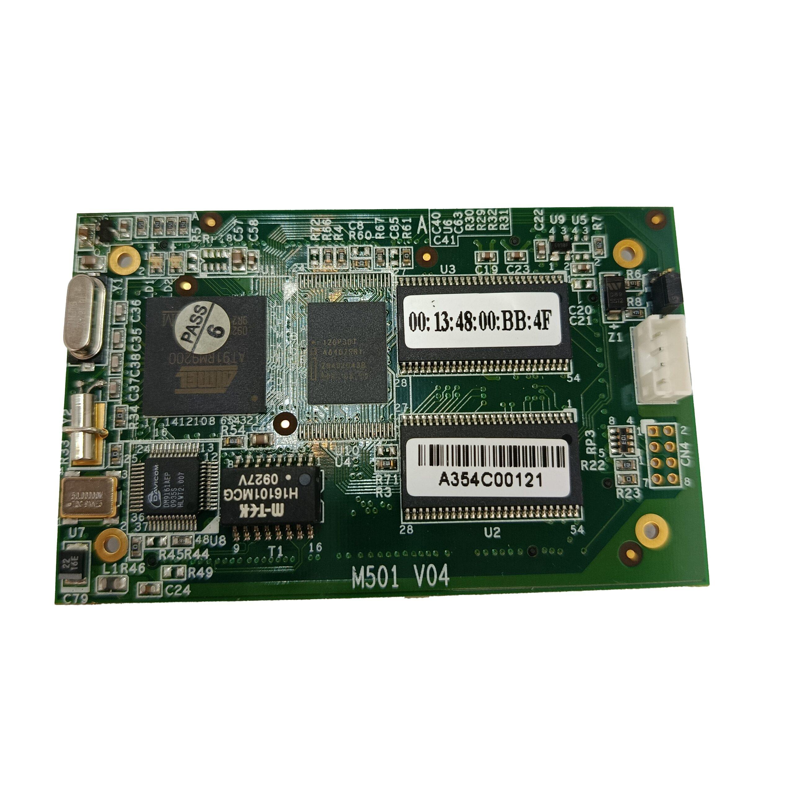
کامپیوتر صنعتی مبتنی بر لینوکس ARM 9 مدل M501
﷼150.000.000
کامپیوتر صنعتی لینوکس M501
M-501 is an ARM9-based Linux ready System on Module. The M-501 is equipped with an ATMEL
AT91RM9200 SoC and features:
ARM920T ARM Thumb Processor with 200MIPS at 180MHz, Memory Management Unit
16-KByte Data Cache and 16-KByte Instruction Cache
64MB SDRAM, 16MB Flash
One 10/100Mbps Ethernet with MAC/PHY and transformer
Two USB 2.0 full speed (12Mbps) Host Ports
Multimedia Card Interface for SD memory card
Four UARTs with hardware and software flow control
Two-wire Interface (I2C) for Real Time Clock
32 Programmable Digital I/O Port
8-bit external local bus interface
کامپیوتر صنعتی لینوکس M501
Hardware Specifications
CPU / Memory
SoC: ATMEL AT91RM9200
CPU: ARM920T ARM Thumb Processor with Memory Management Unit (MMU)
Clock: 180MHz
SDRAM: 64MB
Flash: 16MB Intel StrataFlash or Equivalent
Network
Ethernet: 10/100Mbps with MAC/PHY and Transformer
PHY: DAVCOM DM9161
Transformer: 1.5 KV isolation
Signal: ETX0+, ETX0-, ERX0+, ERXUSB Port
Host: USB 2.0 full speed (12Mbps) Host x2
Signal: UDataA+, UDataA-, UDataB+, UDataBUART
Four Universal Asynchronous Receiver and Transmitter
Data Bits: 5 to 9 bits
Parity: None, Even, Odd, Mark, Space
Stop: 1, 1.5, 2 bits
Baud Rate: Up to 921.6 Kbps
Flow Control: RTS/CTS, XON/XOFF, None
Multi-drop Mode with address generation and detection (COM1 only)
RS-485 Driver Control Signal (COM1: RTS0)
Signal Level: CMOS/3.3V compatible
COM1: TXD0, RXD0, RTS0, CTS0 (RS485 Control: RTS0) (Software configurable
RS-232/422/485)
COM2: TXD1, RXD1, RTS1, CTS1, DCD1, DTR1, DSR1 (RS-232 with full modem control)
COM3: TXD2, RXD2, RTS2, CTS2 (RS-232 with hardware flow control)
COM4: TXD3, RXD3, RTS3, CTS3 (RS-232 with hardware flow control)
I2C Bus (Inter-IC Bus)
Compatible with standard two-wire serial memory interface
Supported Devices: (Driver built-in)
Real Time Clock: Ricoh (RS5C372)
EEPROM: ATMEL AT24C16 and compatible
Signal: TWD, TWDK
M-501 User Guide
‧4‧
I2S (Internal IC Sound)
Transmitter: TSCK, TWS, TSD
Receiver: RSCK, RWS, RSD
SPI (Serial Peripheral Interface)
Two chip Selects with external decoder
Three wires signals: MISO, MOSI and SPCK clock
Signal: MISO, MOSI, SPCK, CS1, CS2
Multimedia Card Interface
Compatible with SD memory card Specification 1.0
Signal: MCCDA, MCCK, MCDA0, MCDA1, MCDA2, MCDA3
Watchdog Timer:
CPU built-in WDT and used by Linux Kernel
Programmable DIO
32 General Purpose IOs and can be programmable as digital input or output
Support interrupt function for digital inputs
Signal Level: CMOS/3.3V Compatible
Input:
Low level: -0.3V min / +0.8V max
High level: +2V min / +3.9V max
Output:
Low level: +0.4V max @ 0mA / +0.2V min @ 8mA
High level: +3.1V max @ 0mA / +2.9V min @ 8mA
Signal: PIO0 to PIO31
Note
PIO24 to PIO31 are reserved for RS-232/422/485 interface selection for serial ports 1 to 4. Please contact
Artila if you want to use PIO24 to PIO31.
External Bus Interface
8-bit data bus
Signal: D0~D7
8-bit address bus
Signal: A0~A7
4 Chip Selection
Signal: NCS3~NCS6
Signal Level: CMOS/3.3V
M-501 User Guide
‧5‧
Predefine Pins
Reset Button (CN2, pin#35, RST#1), input
Buzzer (CN2, pin#37, BUZR), output
System ready LED (CN2, pin#38, RDY_LED), output
LAN activity LED (CN3, pin#11, ACT_LED), output
Undefined Digital IO Pins (reserved)
CN1: pin#23, #24, #25, #26
CN3: pin#23, #24
Debug Port:
Serial Console: Tx/Rx
Signal: Tx share with RTS2
Rx share with CTS2
JTAG: For low level debug
Signal: NTRST, TDI, TMS, TCK, TDO
Power
Input: 3.0 to 3.6VDC (3.3V nominal)
Consumption: 2.5W
نقد و بررسیها
هنوز بررسیای ثبت نشده است.